What you’ll learn:
- Key components of the 1-MW motor.
- What comprises the 1-MW inverter system?
- A look at the channel-type heat-exchanger architecture to keep the system cool.
Up to a few years ago, “flying cars”—vehicles that could transition seamlessly between ground and air modes—were receiving lots of attention. That hype-cycle seems to have faded, as have many of the companies developing such projects. It turns out that the needs and priorities of a car and those of an aircraft differ significantly in so many ways that it is difficult to overcome the gap.
Now, it’s electric vertical take-off/landing (eVTOL) vehicles, popularly called “air taxis,” which are getting attention, with at least a dozen startups vying to have the first successful and certified model (see References). These eVTOLs are intended to ferry a very small number of passengers over a modest distance using rooftops or small VTOL “heliports” (okay, getting the needed ground-support facilities in place is another significant barrier, but we’ll ignore that aspect for now).
Alongside the interest in eVTOLs is work being done at NASA and elsewhere to develop small, electric-powered winged aircraft that would use conventional small and larger airports for “commuter” flights.
Going Big with Electric Motors
But why stop there? Why not think “big” in the project to electrify aviation and thus hopefully reduce the fairly large emissions of commercial aviation? While electric motors of several hundred kilowatts are already being tested for small aircraft, a larger aircraft needs a motor in the megawatt class.
Developing such a motor is what an MIT team is doing, lead by Zoltan Spakovszky, the T. Wilson Professor in Aeronautics and the Director of the Gas Turbine Laboratory (GTL) (there’s some irony seeing that a gas turbine laboratory is leading this electrification effort), along with the MIT Laboratory for Electromagnetic and Electronic Systems. The project is sponsored by Mitsubishi Heavy Industries (MHI).
While 1-MW electric motors aren’t standard, off-the-shelf items, they’re not rare, either. Such motors are used in heavy industrial settings, mineral crushing and processing, and huge pumping installations, which are all ground-based. Obviously, a 1-MW electric motor for aircraft would have very different constraints with respect to weight, size, mounting, and thermal considerations.
As Spakovszky notes, “This is hard engineering, in terms of co-optimizing individual components and making them compatible with each other while maximizing overall performance. To do this means we have to push the boundaries in materials, manufacturing, thermal management, structures and rotordynamics, and power electronics.”
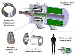
The motor’s main components (Fig. 1) are:
- A high-speed rotor, lined with an array of magnets with varying orientation of polarity.
- A compact low-loss stator that fits inside the rotor and contains an intricate array of copper windings.
- An advanced heat exchanger that keeps the components cool while transmitting the torque of the machine.
- A distributed power electronics system, made from 30 custom-built circuit boards, that precisely change the currents running through each of the stator’s copper windings, at high frequency.
Given the size and complexity of the project, it’s not surprising that it’s a co-optimized integrated design. This means that the interlinked considerations, ranging from thermal management to rotordynamics to power electronics to electrical machine architecture, were assessed in an integrated way to determine the best possible combination to reach the targeted 1-MW power level.
Inverter Design: Choices and Tradeoffs
The motor is designed with its distributed circuit boards close-coupled with the electrical machine to minimize transmission loss and allow for effective air cooling through the integrated heat exchanger.
The team compared the performance of the three-phase bridge inverter to a group of three single-phase full-bridge inverters for motor-drive applications, within inverter sets based on two-level topologies as well as a multilevel topology. The topology comparison indicated that even though multilevel inverters achieve the highest efficiency, they are by far the heaviest in weight.
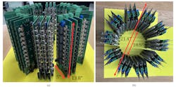
By comparison, groups of single-phase full-bridge inverters achieve the lightest weight and the second highest efficiency of the three considered options. The 1-MW inverter system is divided into ten 100-kW three-phase inverters based on one of the considered inverter topologies (Fig. 2), with each of the ten inverter units driving a sector of the machine.
As part of the co-optimization process, they swept the device switching frequency between 20 and 100 kHz to identify the highest specific-power, full-bridge-inverter-based motor-drive design. They identified an optimum device switching frequency of 80 kHz.
Each switch position has ten parallel 1,200-V SiC devices (Cree C3M0075120J) and each 100-kW inverter set consists of three full-bridge boards (Fig. 3). Because the FETs farthest from the cooling source have the highest operating junction temperatures, resistance temperature detectors (RTDs) are glued with low thermal-resistance epoxy to the heatsinks of the four devices farthest from the cooling source.
Each single-phase board is equipped with a local microcontroller (Microchip Technology PIC33EV64GM006) (Fig. 4). Each set of three single-phase boards can be run in open-loop voltage control or closed-loop current control, with the encoder angle and current or voltage commands received from a master controller board via an isolated Serial Peripheral Interface (SPI) link.
Keeping Cool
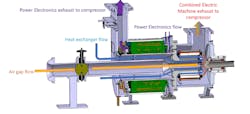
No discussion of a 1-MW device can minimize thermal issues. The team examined various cooling architectures as well as the effect of temperature on thermal expansion and associated mechanical interference and structural loading (Fig. 5). They also looked at how to manufacture the necessary parts. Their proposed channel-type heat-exchanger architecture leverages additive-manufacturing techniques to blend multiple cooling architectures and meet the combined structural and thermal requirements.
To manage risk, the team built and tested each of the major components individually, and shown that they can operate as designed and at conditions exceeding normal operational demands. They plan to assemble the first fully working electric motor as an “all-up” system and start testing it in the fall.
Details of their ambitious project aren’t published in an academic journal but were instead presented recently at the American Institute of Aeronautics and Astronautics – Electric Aircraft Technologies Symposium (EATS). Fortunately, the team has posted a set of highly detailed, thorough, well-written, and very readable papers (each between 15 and 23 pages) covering electrical, mechanical, thermal, and other facets of the project from conception through design, modeling, optimization, analysis, manufacturing, and progress:
- Design and Manufacturing of a High-Specific-Power Electric Machine for Aircraft Propulsion
- A Megawatt-Class Electrical Machine Technology Demonstrator For Turbo-Electric Propulsion
- Design and Optimization of an Inverter for a One-Megawatt Ultra-Light Motor Drive
- Novel Channel-type Heat Exchanger for a Megawatt-Class Integrated Motor Drive Technology Demonstrator
- High Speed Rotor System for a Megawatt-Class Integrated Motor Drive Technology Demonstrator
If you think student projects can only be “small scale,” then these papers and the project will make you realize otherwise.
References
“EVTOL Companies Are Worth Billions—Who Are the Key Players?”
“Following the Money in the Air-Taxi Craze”
“Electric Airplanes Won’t Make Much of a Dent in Air Travel for Decades to Come”
